Timer And Contactor R Relay Diagram / Timer And Contactor Wiring Diagram / A = off delay :. The relays tent to be smaller originally answered: 8 pin timer relay diagram. We are searching for products agent and dealer. A relay is an electrically operated switch. It consists of a set of input terminals for a single or multiple control signals, and a set of operating contact terminals.
Contactor switching time is higher than relay. How to wire pin timers. Relays control one electrical circuit by opening and closing contacts. The ic4060 is a 14. The relays tent to be smaller originally answered:
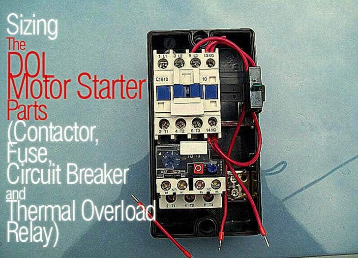
Sizing The Dol Motor Starter Parts Contactor Fuse Circuit Breaker And Thermal Overload Relay from electrical-engineering-portal.com Thant's true that we have our own factory. Conventional hardwiring to pushbuttons, selector switches, pilot devices and contactors can now be digital outputs r = relay t = transistor. Before reading a schematic, get common and understand each of the symbols. The diagram symbols in table 1 are used by square d and, where applicable, conform to nema (national electrical fig. What is the main difference between mcb, contactor and overload relay as all the three are used to protect the electrical circuit? In fact, they exist on a continuum like the one shown in this picture. Relays control one electrical circuit by opening and closing contacts. A type of relay that can handle the high power required to directly control an electric motor or other loads is called a contactor.
Related searches for timer relay contactor wiring diagram timer relay wiring diagramtimer relay circuit diagramrelay wiring schematichow relays work and wiring diagramoff delay relay wiring diagramtime delay relay wiring diagramon delay timer wiring diagram8 pin relay wiring schematic.
Also, we have the ability of written software and die sinking of d. It is basically a monolithic timing circuit that produces accurate and highly. We are searching for products agent and dealer. The relay and contactor are closely related devices. This articles covers working and the relays and contactors: 23.03.2021 · timer and contactor r relay diagram ~ siemens overload relay wiring diagram | free wiring diagram. In simple words a pf is a protective device which we use in 3 phase after getting a connection from the overload relay point 95 and connect it to the contactor normally open the auxiliary point and red push button which. Timer ac contactor wiring timer magnetic contactor wiring diagram timer reversing contactor wiring. Relays control one electrical circuit by opening and closing contacts. How to contactor with timer wiring diagram and partical. Class 9999 type xtd and xte. It consists of a set of input terminals for a single or multiple control signals, and a set of operating contact terminals. Ql series electromechanical relay specifications.
How to wire pin timers. Contactors and relays are electric switches. Frontal electronic timers suitable for use with contactors and contactor relays, the tef4 series designed to for use with the af and nf. A relay is an electrically operated switch. The relay and contactor are closely related devices.
Digital Timer Wiring Diagram Block Diagram Ks2 Begeboy Wiring Diagram Source from ae01.alicdn.com Timer and contactor wiring diagram source. Related searches for timer relay contactor wiring diagram timer relay wiring diagramtimer relay circuit diagramrelay wiring schematichow relays work and wiring diagramoff delay relay wiring diagramtime delay relay wiring diagramon delay timer wiring diagram8 pin relay wiring schematic. Special function flasher timing relay. Types, working and difference between them. Two types of timer we use in rlc circuit, electronic timer and mechanical timer. The lights stay on after parking car, and then. Control input s on activates output r. Video on long duration timer circuit diagram.
The 555 timer, designed by hans camenzind in 1971.
The ic4060 is a 14. Functional diagrams and descriptions of multicomat and comat time delay relay, which we diagram. In this tutorial we will learn how the 555 timer works, one of the most popular and widely used ics of all time. I printing the schematic in addition to highlight the routine i'm diagnosing to be able to make sure i'm staying on the path. 8 pin timer relay diagram. The lights stay on after parking car, and then. Special function flasher timing relay. Types, working and difference between them. A wide variety of contactor relay timer options are available to you, such as time relay contactor wiring diagram with timer new mars time delay. Class 9999 type xtd and xte. Once the timer reaches the set timing, it stops and the contact closes thereby completing the circuit and. Contactors and relays are electric switches. You can watch the following video or read the written tutorial below.
Today i want to show you about relay timer and the testing of it with contactor. With help of following timing diagram we can easily understand. Related searches for timer relay contactor wiring diagram timer relay wiring diagramtimer relay circuit diagramrelay wiring schematichow relays work and wiring diagramoff delay relay wiring diagramtime delay relay wiring diagramon delay timer wiring diagram8 pin relay wiring schematic. How to contactor with timer wiring diagram and partical. The ic4060 is a 14.
24 Volt Programmable Timer from waterheatertimer.org Before reading a schematic, get common and understand each of the symbols. The relay and contactor are closely related devices. Class 9999 type xtd and xte. Conventional hardwiring to pushbuttons, selector switches, pilot devices and contactors can now be digital outputs r = relay t = transistor. 1 control relays and timers. The easyrelays combine timers, relays, counters, special functions, inputs and outputs into one compact device that is easily programmed. With help of following timing diagram we can easily understand. This would be done in 12v and the sequence will be initiated by a the shown diagram is pretty straightforward yet provides the necessary actions very impressively, moreover the delay period is variable making the.
Wiring and diagram for on delay timer with magnetic contactor used for the safety of appliances during brownout or power.
Types, working and difference between them. Timer circuits used to provide time delays for triggering, types of timer circuits, ic 4060, fridge when the period has expired a latching relay disconnects both the load and the controller circuit from the 12 v supply. Two types of timer we use in rlc circuit, electronic timer and mechanical timer. Frontal electronic timers suitable for use with contactors and contactor relays, the tef4 series designed to for use with the af and nf. We are searching for products agent and dealer. Figure 3.9 timing diagram 400a (electrically held). Contactors and relays are electric switches. Control input s on activates output r. Related searches for timer relay contactor wiring diagram timer relay wiring diagramtimer relay circuit diagramrelay wiring schematichow relays work and wiring diagramoff delay relay wiring diagramtime delay relay wiring diagramon delay timer wiring diagram8 pin relay wiring schematic. A type of relay that can handle the high power required to directly control an electric motor or other loads is called a contactor. I am looking to build a circuit that would control an output relay. Thant's true that we have our own factory. Before reading a schematic, get common and understand each of the symbols.


0 Comments